The Easy Guide to UML Class Diagrams
What is Meant by UML?
UML stands for Unified Modeling Language. UML 2.0 helped extend the original UML specification to cover a wider portion of software development efforts including agile practices.
-
Improved integration between structural models like class diagrams and behavior models like activity diagrams.
-
Added the ability to define a hierarchy and decompose a software system into components and sub-components.
-
The original UML specified nine diagrams; UML 2.x brings that number up to 13. The four new diagrams are called: communication diagram, composite structure diagram, interaction overview diagram, and timing diagram. It also renamed statechart diagrams to state machine diagrams, also known as state diagrams.
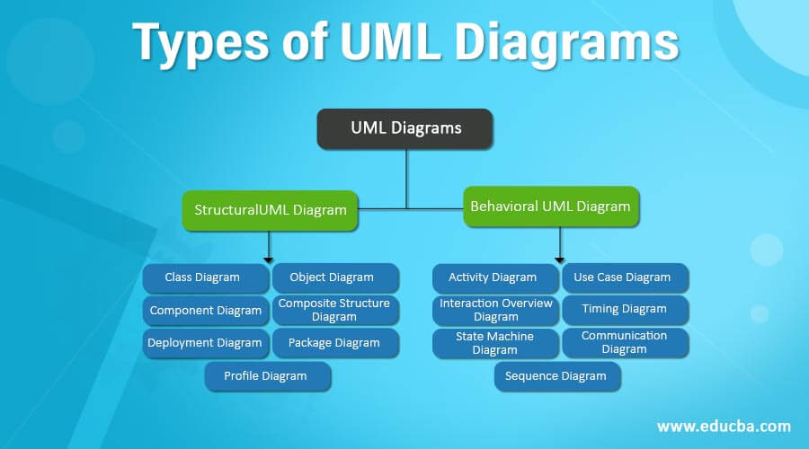
Types of UML Diagrams
The current UML standards call for 13 different types of diagrams: class, activity, object, use case, sequence, package, state, component, communication, composite structure, interaction overview, timing, and deployment.
These diagrams are organized into two distinct groups: structural diagrams and behavioral or interaction diagrams.
-
Structural UML diagrams
-
Class diagram
-
Package diagram
-
Object diagram
-
Component diagram
-
Composite structure diagram
-
Deployment diagram
-
-
Behavioral UML diagrams
-
Activity diagram
-
Sequence diagram
-
Use case diagram
-
State diagram
-
Communication diagram
-
Interaction overview diagram
-
Timing diagram
-
Class Diagram Definition | What is a Class Diagram?
A class diagram is a UML diagram type that describes a system by visualizing the different types of objects within a system and the kinds of static relationships that exist among them. It also illustrates the operations and attributes of the classes.
They are usually used to explore domain concepts, understand software requirements and describe detailed designs.
Class Diagram Notations with Examples
There are several class diagram notations that are used when drawing UML class diagrams. We’ve listed below the most common class diagram notations.
Class
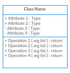
Classes represent the central objects in a system. It is represented by a rectangle with up to 3 compartments.
The first one shows the class’s name, while the middle one shows the class’s attributes which are the characteristics of the objects. The bottom one lists the class’s operations, which represents the behavior of the class.

The last two compartments are optional. The class notation without the last two compartments is called a simple class and it only contains the name of the class.
Interface
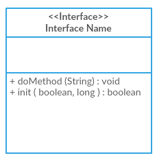
The interface symbol in class diagrams indicates a set of operations that would detail the responsibility of a class.
Package
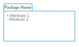
The package symbol is used to group classes or interfaces that are either similar in nature or related. Grouping these design elements using the package symbols improves the readability of the diagram.
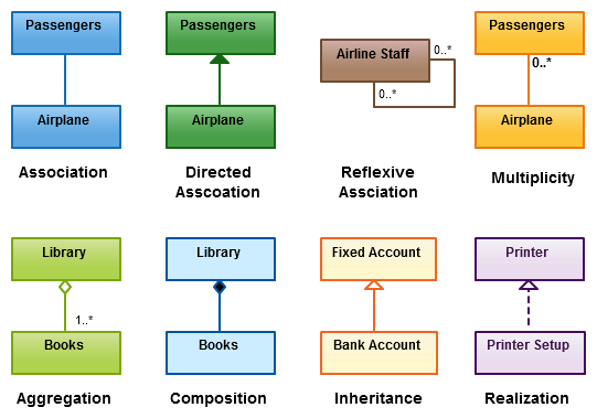
Class Diagram Relationships
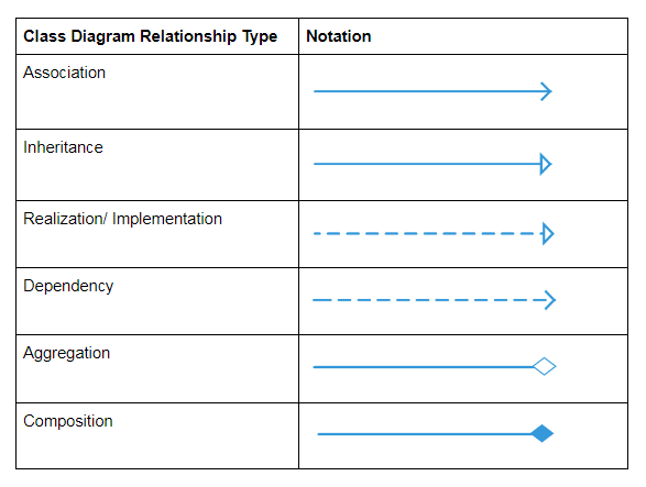
The class diagram connector types and the different relationships between classes:
How to Draw a Class Diagram
-
Step 1: Identify the class names: The first step is to identify the primary objects of the system.
-
Step 2: Distinguish relationships: Next step is to determine how each of the classes or objects are related to one another. Look out for commonalities and abstractions among them; this will help you when grouping them when drawing the class diagram.
-
Step 3: Create the Structure: First, add the class names and link them with the appropriate connectors. You can add attributes and functions/ methods/ operations later.
Class Diagram Best Practices
-
Class diagrams may tend to get incoherent as they expand and grow. It’s best to avoid creating large diagrams and breaking them down into smaller ones that you can link to each other later. You can very easily do this with Creately. It helps you improve the readability of your diagrams.
-
Using the simple class notation, you can quickly create a high-level overview of your system. A detailed diagram can be created separately as required, and even linked to the first one for easy reference.
-
The more lines overlap on your class diagrams, the more cluttered it becomes. The reader will only get confused trying to find the path. Make sure that no two lines cross each other.
-
Use colors to group common modules. Different colors on different classes help the reader differentiate between the various groups.
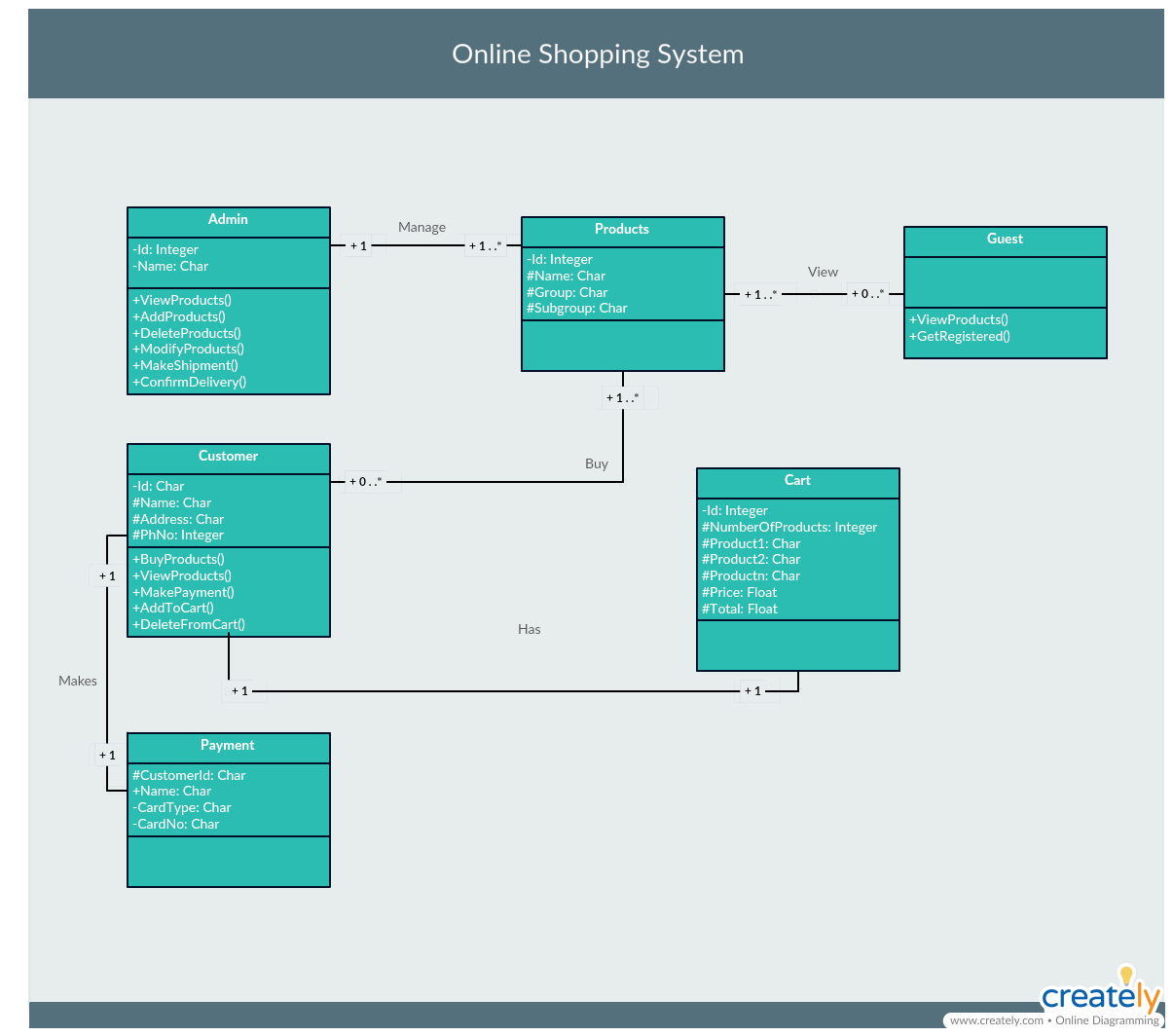
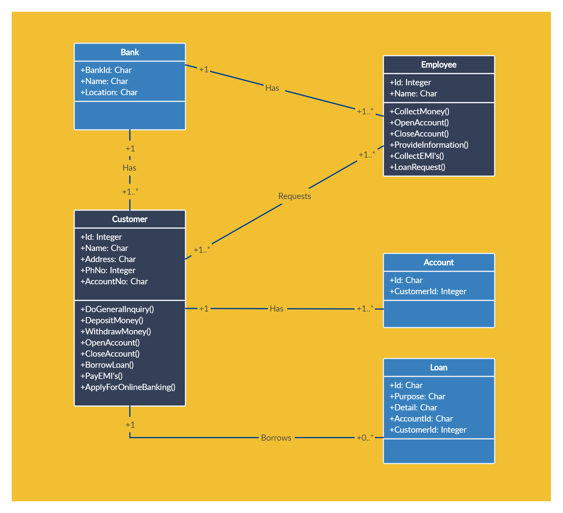
Class Diagram Examples / Templates
How to turn your golang programs into UML Class diagrams
Goplantuml is a Golang library with an added command that you can install if you run go already. It basically turns code like this
package main

import "strings"

type Foo struct {
    field       int
    PublicField bool
    *strings.Builder
}
type MyInterface interface {
    GetValue() bool
}

func (f *Foo) myPrivateFunction() int {
    return 3
}

func (f *Foo) GetValue() bool {
    return true
}

func (f *Foo) MyPublicFunction() bool {
    return true
}
into this
@startuml
namespace goisawesome {
    class Foo {
        - field int
        + PublicField bool
        - myPrivateFunction()
        + GetValue()
        + MyPublicFunction()
    }
    interface MyInterface {
        + GetValue()
    }
}
strings.Builder *-- goisawesome.Foo
goisawesome.MyInterface <|-- goisawesome.Foo
@enduml
which can be used with plantuml to generate a nice class diagram.